× Overview The Robot For Schools Our Mission Open Learning Portal ↗ Contact Sales
The Robot

21 programmable degrees of freedom.
Governed by a protected motion system.

A real physical platform running ROS 2 on an onboard Raspberry Pi. Students write code for all 21 joints — every command passes through validation, an execution queue, and instructor approval before it reaches the motors. Click the anatomy hotspots below to explore every system.

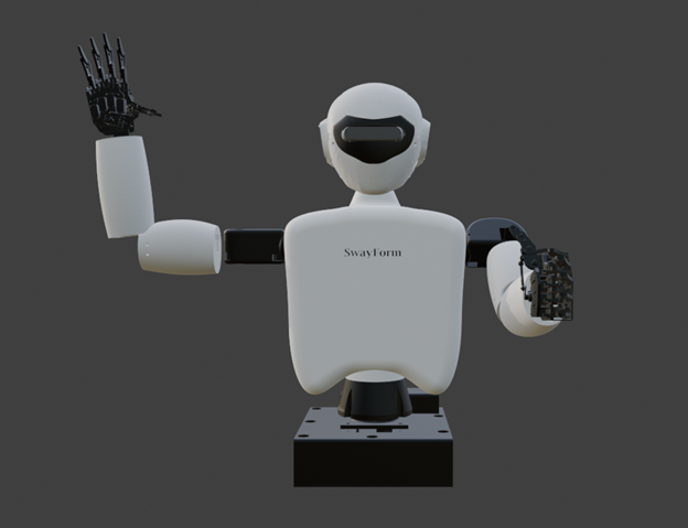
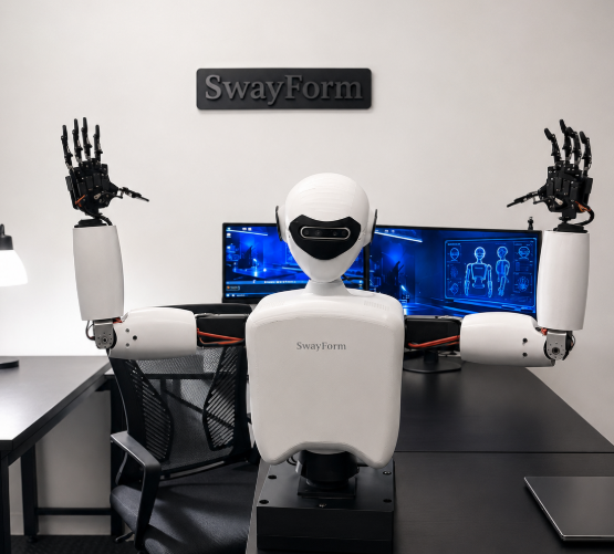
SwayForm humanoid robot prototype
21
Degrees of freedom
8 GB
RPi 5 RAM
12V
Main supply rail
D435i
RealSense depth
ROS 2
Software stack
PLA
3D printed frame
Interactive Anatomy

The robot, labeled.

Click any hotspot. The viewer animates into that part and holds on the labeled image.

SwayForm robot overview
Loading system view…

Click a hotspot on the robot to explore that system.

Joint Reference

All joints

ROS joint names, controller assignment, safe ranges, and servo models.

All 21 joints are available to student programs. Every command passes through the protected motion-control node, which enforces these joint limits, speed limits, and command timeouts before anything reaches a motor — see Safety.

Joint name ROS name Controller Ch Range Neutral Servo
Neck Yaw neck_yaw 0x40 0 −45° / +45° MG996R
Neck Pitch neck_pitch 0x40 1 −20° / +25° MG90S
R. Shoulder Pitch right_shoulder_pitch 0x40 2 −10° / +90° MG996R
R. Shoulder Roll right_shoulder_roll 0x40 3 −30° / +20° MG996R
R. Elbow right_elbow 0x40 4 −120° / 0° −10° MG996R
R. Wrist right_wrist 0x40 5 −45° / +45° MG90S
R. Thumb right_thumb 0x40 6 0° / +70° 15° MG90S
R. Index Finger right_index 0x40 7 0° / +90° 15° MG90S
R. Middle Finger right_middle 0x40 8 0° / +90° 15° MG90S
R. Ring Finger right_ring 0x40 9 0° / +90° 15° MG90S
R. Pinky Finger right_pinky 0x40 10 0° / +80° 15° MG90S
L. Shoulder Pitch left_shoulder_pitch 0x40 11 −10° / +90° MG996R
L. Shoulder Roll left_shoulder_roll 0x40 12 −20° / +30° MG996R
L. Elbow left_elbow 0x40 13 0° / +120° 10° MG996R
L. Wrist left_wrist 0x40 14 −45° / +45° MG90S
L. Thumb left_thumb 0x40 15 0° / +70° 15° MG90S
L. Index Finger left_index 0x41 0 0° / +90° 15° MG90S
L. Middle Finger left_middle 0x41 1 0° / +90° 15° MG90S
L. Ring Finger left_ring 0x41 2 0° / +90° 15° MG90S
L. Pinky Finger left_pinky 0x41 3 0° / +80° 15° MG90S
Waist Rotation waist_yaw 12V direct −60° / +60° DC+encoder
Components

Every part. What it does. How it connects to code.

Key components. Click any card for details.

Raspberry Pi 5 (8GB)
Compute

The robot's brain. Runs Linux and a ROS 2-based software stack locally — current development builds use Ubuntu 22.04 — plus the hardware driver and all student nodes. Connects to everything over GPIO, I²C, USB, and Wi-Fi. The commercial release will use a tested, supported long-term-support software image available at launch.

Python lib: rclpy
Intel RealSense D435i
Vision

Publishes synchronized color and depth image streams. Color at 640×480, depth per pixel in millimeters. USB-connected to Pi. Min range ~0.3m.

Topic: /camera/color/image_raw
PCA9685 ×2
Motion

16-channel PWM controllers on I²C. Two units give 32 total channels — controller 0x40 uses all 16 channels (neck, right arm, left arm), controller 0x41 uses 4 of 16 (left hand), leaving 12 channels free for future expansion. 12-bit resolution, 50Hz default frequency.

Python lib: adafruit_pca9685
MG996R Servo
Motion

High-torque metal-gear servo for large joints (shoulders, elbows). Stall torque 13kg/cm at 6V. PWM range 500–2500µs.

Current draw: up to 1.4A stall
MG90S Servo
Motion

Micro metal-gear servo for small joints (wrists, fingers, neck pitch). Stall torque 2.2kg/cm at 5V. Same PWM timing as MG996R.

Weight: 13.4g
MPU-6050 IMU
Sensing

Accelerometer + gyroscope on one I²C chip. Publishes on /swayform/imu. Used for tilt detection, shake triggers, and orientation-aware behaviors.

Topic: /swayform/imu
HC-SR04 Ultrasonic
Sensing

Time-of-flight distance sensor. Range 2cm–4m, ±3mm accuracy. Key for proximity-triggered greetings and obstacle detection behaviors.

Topic: /swayform/distance
12V / 50A Power Supply
Power

Feeds a central bus bar with four outgoing paths: a buck converter to the Raspberry Pi (5V), two separately regulated 6V buck converters for the servo groups (one of which also supplies the neck motors), and a direct 12V line to the base-rotation DC motor. Never connect/disconnect while servos are active.

Two separately regulated 6V servo rails
USB Audio + Amp + Speaker
Audio

Raspberry Pi 5 has no built-in analog audio output, so sound runs Pi 5 → USB audio adapter → 3.5mm → PAM8403 amp (separately powered) → 3W speaker. Software: pyttsx3 for TTS, pygame.mixer for clips. Triggered via /swayform/audio_command.

Topic: /swayform/audio_command
Electrical

Power architecture

A single 12V/50A supply feeds a central bus bar with four outgoing paths — one buck converter each for the Pi and the two servo groups, plus a direct 12V line to the base motor. Rails are separately regulated so current spikes from motors should never reset the Pi.

Final current protection, fuse sizing, and conductor ratings will be validated before classroom release. Detailed converter models, wire gauges, and measured current draw are documented in the Learning Portal technical reference.

Wiring block diagram
12V PSU 50A Bus Bar 4 outputs Buck 5V Pi rail Pi 5 USB-C 5V 12V Direct no converter Base Motor waist_yaw Buck 6V — A incl. neck Servo Power A MG996R/90S Buck 6V — B 2nd rail Servo Power B MG996R/90S
Both PCA9685 controllers draw power from the two 6V servo rails and receive position commands over a separate I²C signal path — see Components above.

Common electrical issues

Servo twitching randomly
Voltage sag under load. Buck converter undersized or servo rail underpowered. Check voltage at PCA9685 V+ pin under load (should stay above 5.8V).
Pi reboots when robot moves
Inrush current from several servos starting at once sags the shared 12V bus, dipping the Pi's 5V buck converter output. Add bulk capacitance near the Pi's buck converter and stagger servo startup in software.
One side of robot dead
Second PCA9685 not initializing. Check I²C address (0x41 vs 0x40 jumper). Run i2cdetect -y 1 on Pi and confirm both addresses appear.
Grinding noise from joint
Servo hitting mechanical stop. Out-of-range command bypassing clamp, or wrong joint name published. Cut servo power immediately. Verify angle limits and joint name mapping.